 Tower, Iris Bay - Office 1705 - Al Mustaqbal St - Business Bay - Dubai
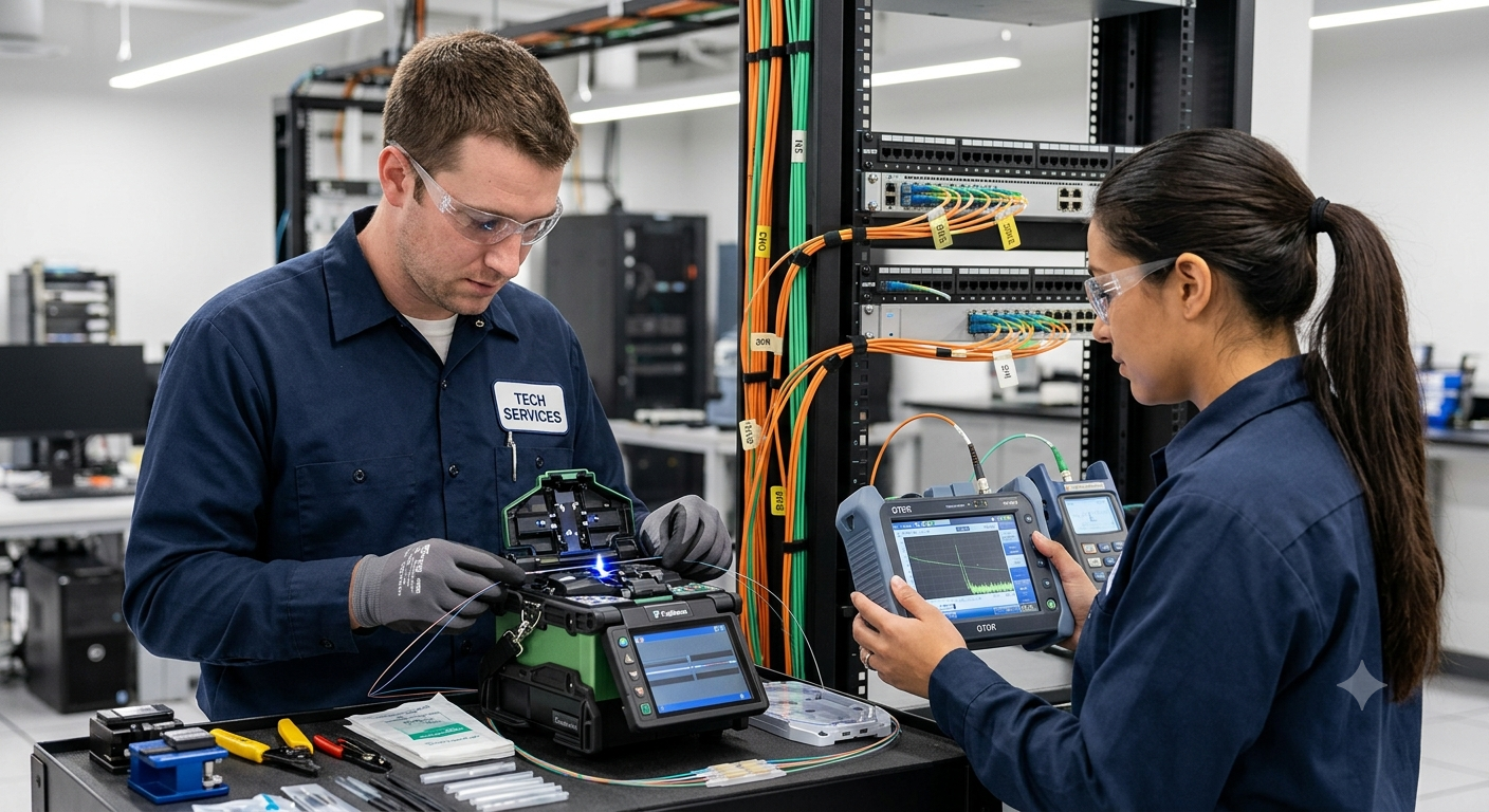
The Ultimate Guide to Fiber Optic Splicing and Testing: Ensuring Peak Network Performance
In an era dominated by cloud computing, 5G networks, IoT expansion, and high-frequency data transfers, fiber optic infrastructure forms the backbone of global telecommunications. Unlike traditional copper cabling, fiber optics transmit data as light pulses through strands of glass, offering virtually limitless bandwidth and exceptional speed. However, the integrity of these light pathways depends heavily on two critical technical processes: professional splicing and rigorous testing.
For modern enterprises and telecom providers, establishing a flawless fiber optic link requires deep technical expertise and specialized equipment. As an industry leader in telecommunications infrastructure, Dar Al Montazah Technical Services LLC delivers high-precision fiber optic deployment solutions designed to minimize signal degradation and maximize network uptime.
THE CORE OF CONNECTIVITY – FIBER OPTIC SPLICING
Fiber optic splicing is the process of permanently joining two fiber optic cables together to form a continuous optical waveguide. Splicing is typically required when a cable run is longer than a single reel of fiber, when a cut cable needs restoration, or when branching fibers into distribution networks.
To achieve a seamless connection with minimal insertion loss (the loss of signal power resulting from the insertion of a device or joint), technician teams rely on two primary methodologies: Fusion Splicing and Mechanical Splicing.
1. Fusion Splicing vs. Mechanical Splicing
-
Fusion Splicing: This is the gold standard for modern network deployments. It involves using an electric arc to melt and fuse the glass ends of two fibers together. Fusion splicing creates a continuous, seamless joint that yields the lowest loss—typically less than 0.02 dB—and offers the highest mechanical strength.
-
Mechanical Splicing: This method aligns the fiber ends inside a precise mechanical housing containing an index-matching gel, which bridges the gap between the glass cores. While quicker to set up without expensive machinery, mechanical splicing introduces higher loss (around 0.1 to 0.3 dB) and is generally reserved for emergency temporary restorations or low-budget, short-distance local area networks (LANs).
2. The Step-by-Step Process of Precision Fusion Splicing
Achieving a near-perfect fusion splice requires a sequence of meticulous steps, each demanding absolute precision and cleanliness:
-
Step 1: Stripping the Fiber: Technicians use specialized mechanical stripping tools to carefully remove the polymer outer jacket, buffer tubes, and acrylate coatings, exposing the raw 125-micron glass cladding without nicking or scratching the glass core.
-
Step 2: Cleaning the Fiber: Once exposed, the bare glass must be thoroughly cleaned using 99% pure Isopropyl Alcohol (IPA) and lint-free wipes to remove any remaining microscopic particles, dust, or oils.
-
Step 3: Cleaving the Fiber: This is perhaps the most critical step. Using a high-precision fiber cleaver, the technician scores and breaks the fiber to produce a perfectly flat endface that is precisely perpendicular to the fiber axis (ideally an angle of less than 0.5 degrees). A poor cleave prevents proper alignment and leads to high splice loss.
-
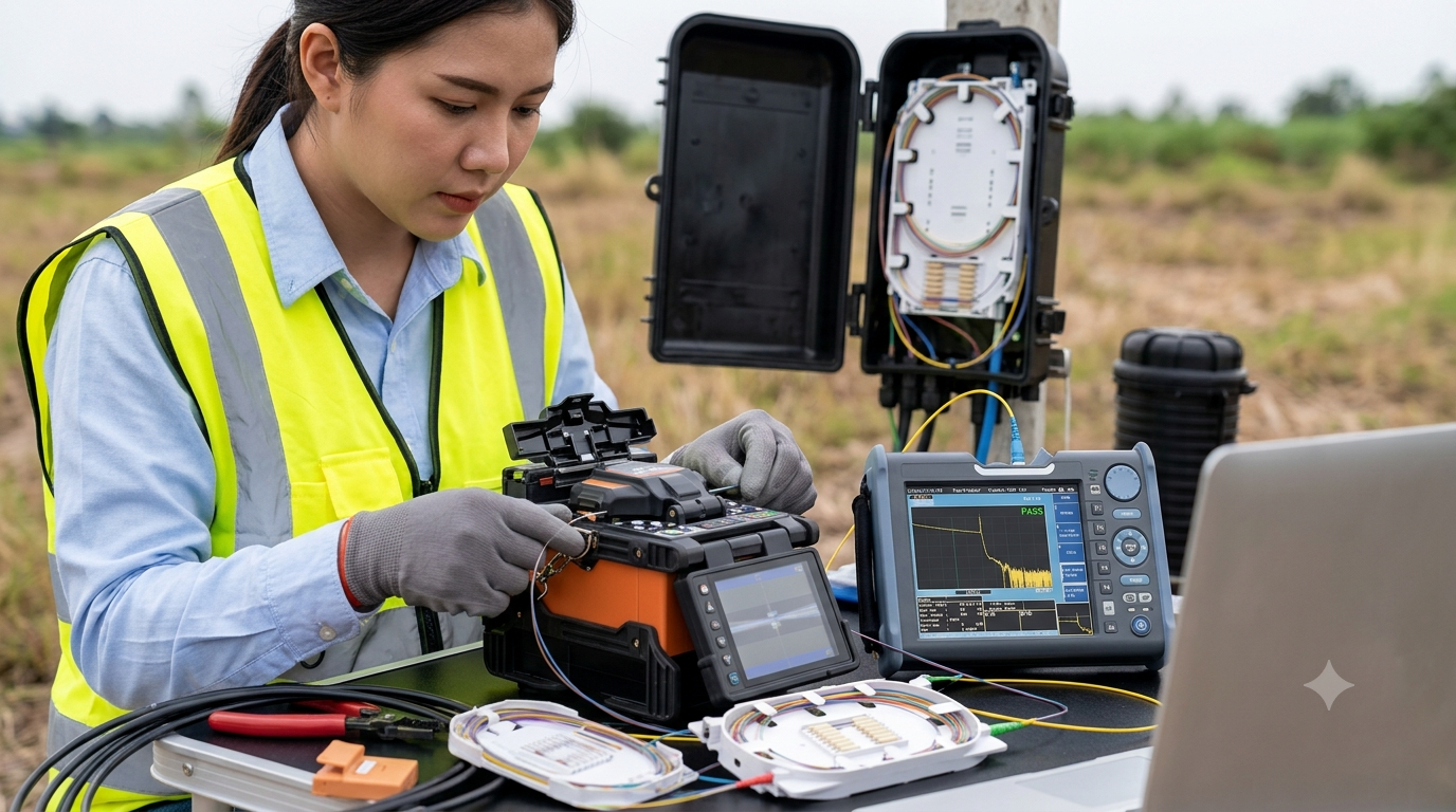
Step 4: Aligning and Fusing: The prepared fibers are placed into the fusion splicer’s V-grooves. Modern splicers use advanced Core Alignment systems to inspect the fibers via built-in cameras, automatically align the cores in three dimensions, and discharge a controlled electric arc to melt and fuse the glass ends together.
-
Step 5: Fiber Protection: Because the bare fused glass is brittle, a heat-shrinkable protection sleeve with a strength member (usually a stainless steel rod) is slid over the splice point and cured in a built-in oven to provide mechanical rigidity and environmental sealing.
RIGOROUS FIBER OPTIC TESTING AND QUALITY ASSURANCE
Splicing is only half the battle. To ensure that a fiber link is fully operational, capable of supporting high-speed data protocols, and compliant with international standards, comprehensive testing is mandatory. Testing detects physical defects, quantifies signal loss, and maps the entire length of the link.
Expert engineering organizations like Dar Al Montazah Technical Services LLC utilize a multi-tiered testing framework to certify fiber optic installations and isolate performance bottlenecks.
1. Key Performance Metrics in Fiber Testing
When evaluating an optical link, technicians measure several critical parameters:
-
Attenuation: The gradual loss of light signal intensity as it travels through the fiber, measured in decibels per kilometer (dB/km).
-
Insertion Loss: The total accumulated signal loss caused by all splices, connectors, adapters, and splitters along the cable route.
-
Optical Return Loss (ORL): The amount of light reflected back toward the source due to imperfections, misaligned connectors, or abrupt changes in the refractive index. High ORL can destabilize laser transmitters.
2. Essential Fiber Optic Testing Methodology
A robust testing regimen involves three distinct tools, each serving a unique diagnostic purpose:
A. Visual Fault Locator (VFL)
A VFL is a handheld device that injects a highly visible red laser (usually 635–650 nm) into the fiber strand. If there is a sharp bend, a broken fiber, or a poorly executed mechanical splice near the termination panel, the red light leaks through the jacket, allowing technicians to visually spot the exact location of the fault instantly.
B. Tier 1 Testing: Optical Loss Test Set (OLTS)
An OLTS—consisting of a stabilized Light Source and an Optical Power Meter—is used to measure the exact overall insertion loss of a fiber link. By injecting a known level of optical power at one end and measuring the received power at the other, the OLTS provides a definitive “Pass/Fail” certification against industry standards (such as TIA or ISO/IEC). Tier 1 testing is mandatory for verifying that the overall power budget of the network equipment is met.
C. Tier 2 Testing: Optical Time Domain Reflectometer (OTDR)
While an OLTS provides a simple total loss figure, an OTDR acts as a radar for fiber optics. It injects high-power light pulses into the fiber and measures the backscattered and reflected light returning over time. The OTDR generates a detailed graphical trace that maps the entire fiber run. It pinpoints the exact distance to, and individual loss of, every single splice, connector, connector macrobend, and cable fault along the path. This makes it an indispensable tool for preventative maintenance and emergency troubleshooting.
Conclusion: Trusting the Experts for High-Performance Networks
Fiber optic splicing and testing are highly sophisticated disciplines that sit at the intersection of micro-optics and precision engineering. A single airborne dust particle, an imperfectly calibrated cleaver, or an unverified splice can degrade an entire network segment, resulting in data packets dropping, localized latency, or complete network blackouts.
By partnering with a certified infrastructure provider like Dar Al Montazah Technical Services LLC, businesses ensure that their fiber networks are built to the highest specifications. Leveraging advanced fusion splicers, state-of-the-art OTDR diagnostic tools, and seasoned field engineers, they deliver certified, future-proof optical backbones that empower your business with uninterrupted, lightning-fast digital connectivity.