 Tower, Iris Bay - Office 1705 - Al Mustaqbal St - Business Bay - Dubai
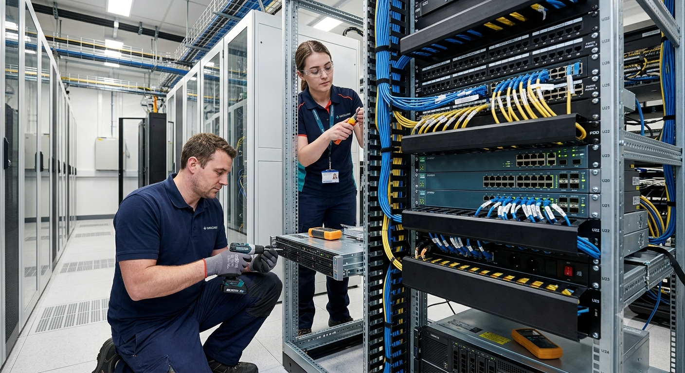
The Definitive Guide to Professional Server Rack Installation and Patching
In modern enterprise IT infrastructure, the server room or data center functions as the central nervous system of business operations. Managing data, communication networks, and cloud applications efficiently requires structured organization at the physical layer. This article, curated by industry experts at Dar Al Montazah Technical Services LLC, explores the critical phases, best practices, and systematic approaches to professional server rack installation and network patch panel deployment.
RACK INSTALLATION FOUNDATION & STRUCTURAL PLANNING
1. Precision Planning and Architectural Readiness
Before unboxing physical hardware, engineering teams must evaluate environmental metrics. Structural planning dictates the longevity, accessibility, and thermal efficiency of network nodes. Floor load capacity is a paramount constraint; fully populated 42U or 48U server enclosures can easily exceed several hundred kilograms, demanding verified structural reinforcement.
Spatial clearance around the enclosure is governed by tight standard specifications. Adhering strictly to EIA/TIA regulations requires leaving at least 36 inches of open space at both the front and rear of the rack structure. This guarantees field technicians sufficient clearance to swing chassis open, pull out slider rails, and execute critical fiber-optic configurations without facing physical restrictions.
2. Thermal Dynamics and Enclosure Selection
Thermal management is the cornerstone of active network reliability. Selecting between open-frame racks and completely enclosed cabinets depends on the surrounding cooling architecture. Open-frame structures work exceptionally well inside dedicated server rooms featuring robust, perimeter-based downflow computer room air conditioning (CRAC) units.
Conversely, enclosed cabinets are preferred when targeted airflow control is necessary. Utilizing perforated front and rear doors supports a predictable cold-aisle/hot-aisle infrastructure configuration. For advanced data rooms, engineers at Dar Al Montazah Technical Services LLC often integrate dedicated Top-of-Rack (ToR) exhaust solutions or active blanking panels to prevent hot exhaust air from recirculating into active equipment intakes.
3. Physical Anchorage, Grounding, and Structural Leveling
Stabilizing structural frames prevents mechanical strain on underlying connection media. Racks must be leveled using heavy-duty adjustable leveling feet, and securely anchored to the concrete floor utilizing concrete expansion shields or under-floor bracket sub-assemblies. This mechanical isolation shields active storage arrays from localized vibrational stress.
Electrical grounding and bonding are vital for system survival and personal safety. Every chassis, rack rail, and enclosure shield must be bonded directly to a dedicated local copper Grounding Busbar (TGB). By creating a continuous path of low impedance to the earth, this framework quickly channels away transient electrostatic discharges (ESD) and power surges, shielding sensitive silicon processors from premature failure.
ADVANCED STRUCTURED PATCHING & CABLE MANAGEMENT
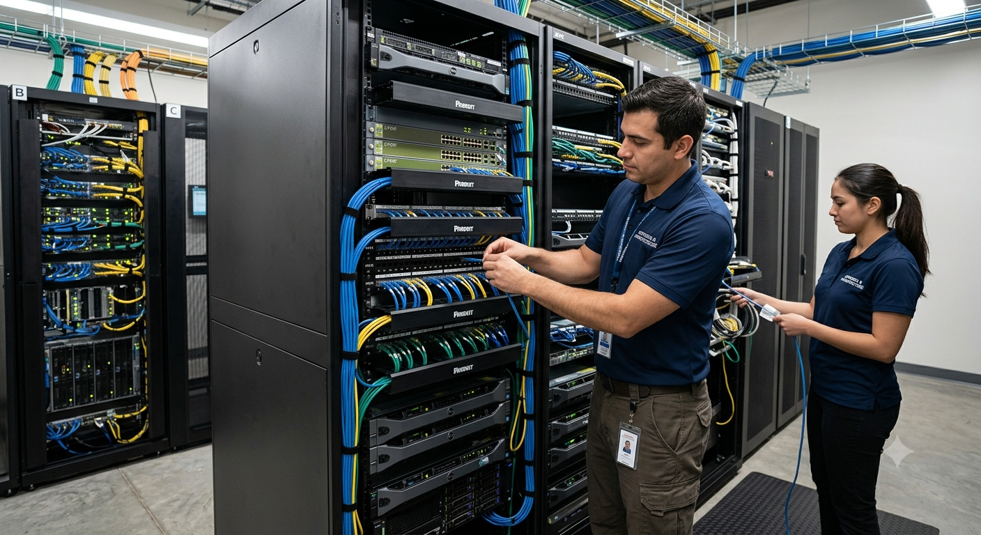
4. Systematic Mapping and Hardware Allocation
Executing structured patching requires clear documentation before physically snapping modules into place. A detailed U-space elevation matrix lists the precise vertical alignment of every hardware element. Best-practice design positions heavy components, such as Uninterruptible Power Supplies (UPS) and deep modular storage shelves, at the base of the rack to maintain a low center of gravity.
Core network components, such as high-density fiber patch panels and main distribution frames (MDF), are ideally positioned at the upper chest level (between 20U and 30U). This strategic placement optimizes reach for both upstream copper trunks and local fiber jumpers, significantly decreasing overall cable length and simplifying long-term diagnostic tracking.
5. Professional Patching Engineering and Strain Relief
Patching turns chaotic bundles of raw cabling into highly organized, high-performance media highways. When terminating Category 6A (Cat6A) or fiber lines behind a patch panel, technicians must closely monitor the cable bend radius. Bending twisted-pair or delicate glass fibers too sharply introduces near-end crosstalk (NEXT) and signal attenuation, which degrades network throughput.
Employing horizontal and vertical cable managers allows installers to route patch cords systematically away from equipment ports. Utilizing specialized hook-and-loop (Velcro) ties ensures bundles stay secure without causing the pinching or crushing commonly associated with plastic zip-ties. Each run must include a slight, uniform service loop to accommodate future equipment upgrades or modifications seamlessly.
6. Comprehensive Labeling, Verification, and Quality Assurance
An infrastructure deployment is only as reliable as its documentation. System technicians rely on alphanumeric ANSI/TIA-606-C labeling standards to ensure every terminal point is easily identifiable. Labeling formats explicitly outline the source rack, patch panel array, and specific port destination on both ends of the cable run.
Once installation wraps up, every copper and fiber drop undergoes comprehensive testing using calibrated field analyzers. This step certifies performance against Cat6A or single-mode fiber parameters, checking for wiremap accuracy, length boundaries, and insertion loss. The engineering team at Dar Al Montazah Technical Services LLC compiles these certification reports into a handover document, giving client operations teams a reliable blueprint for long-term troubleshooting and seamless scaling.